Einführung
Das Verständnis der Aktivierungsdistanzen von Reed-Sensoren ist für die Entwicklung zuverlässiger magnetischer Sensoranwendungen unerlässlich. Dieser Leitfaden erläutert, wie Magnetausrichtung, Empfindlichkeit und Aktuatortyp die Leistung von Reed-Schaltern und Reed-Sensoren beeinflussen. Ob Sie in der Industrieautomation, in Automobilsystemen oder in der kundenspezifischen Elektronik arbeiten – die Kenntnis der korrekten Aktivierungsdistanz gewährleistet optimale Funktionalität und Langlebigkeit. Entdecken Sie detaillierte Diagramme, Tabellen und bewährte Verfahren, um die passende Magnet-Sensor-Kombination für Ihr Projekt auszuwählen.
Wenn Sie in bestimmten Bereichen Hilfe benötigen, können Sie gerne direkt zu einem der folgenden Abschnitte springen:
- What Are Reed Sensor Activation Distances?
- Magnet Orientation and Sensor Performance
- Understanding Magnetic Sensitivity
- Activation Table for Parallel Magnet Position
- Activation Table for Perpendicular Magnet Position
- Actuator Magnets
- Summary: Best Practices for Reliable Reed Sensor Design
Was sind die Aktivierungsdistanzen von Reed-Sensoren?
Der Aktivierungsabstand eines Reed-Sensors bezeichnet den Abstand zwischen Sensor und Magnet, der zum Auslösen des Reed-Kontakts erforderlich ist. Dieser Abstand ist entscheidend für einen präzisen und zuverlässigen Betrieb in Anwendungen wie der industriellen Automatisierung, Automobilsystemen und Unterhaltungselektronik.
Warum die Aktivierungsdistanz wichtig ist
Ein falscher Aktivierungsabstand kann zu Fehlauslösungen oder verpassten Signalen führen und somit die Systemleistung und die Zuverlässigkeit beeinträchtigen. Das Verständnis für diese Abstände hilft Ingenieuren, Sensoren zu entwickeln, die präzise Betriebsanforderungen erfüllen.
Schlüsselfaktoren, die den Aktivierungsbereich beeinflussen
- Magnetstärke und -größe
- Sensorempfindlichkeit
- Ausrichtung des Magneten relativ zum Sensor
Magnet Orientation and Sensor Performance
The position of the magnet relative to the reed sensor significantly affects activation distance. Want a deeper dive into magnets and their specifications? Check out the Reed Technology Academy for more information.
Parallel Magnet Positioning
When the magnet is aligned parallel to the sensor, activation distances tend to be longer. This orientation is common in applications requiring extended sensing ranges.
Perpendicular Magnet Positioning
Perpendicular alignment typically results in shorter activation distances. This setup is ideal for compact designs where space is limited.
Common Orientation Mistakes to Avoid
Avoid placing magnets at inconsistent angles or too far from the sensor, as this can cause unreliable switching.
Understanding Magnetic Sensitivity
Magnetic sensitivity determines how easily a reed sensor responds to a magnetic field. Higher sensitivity sensors activate at greater distances, while lower sensitivity sensors require closer proximity. Choose sensitivity based on your design needs high sensitivity for low-power magnets, and lower sensitivity for strong magnets or tight spaces.
Actuator Magnet and Their Impact
Actuator magnets vary in size, shape, and material, influencing activation distance and reliability. Choose the best magnet for your sensor by matching the magnet type to the sensor sensitivity and application requirements for optimal performance. Discover more about magnets and their specifications in the Reed Technology Academy.
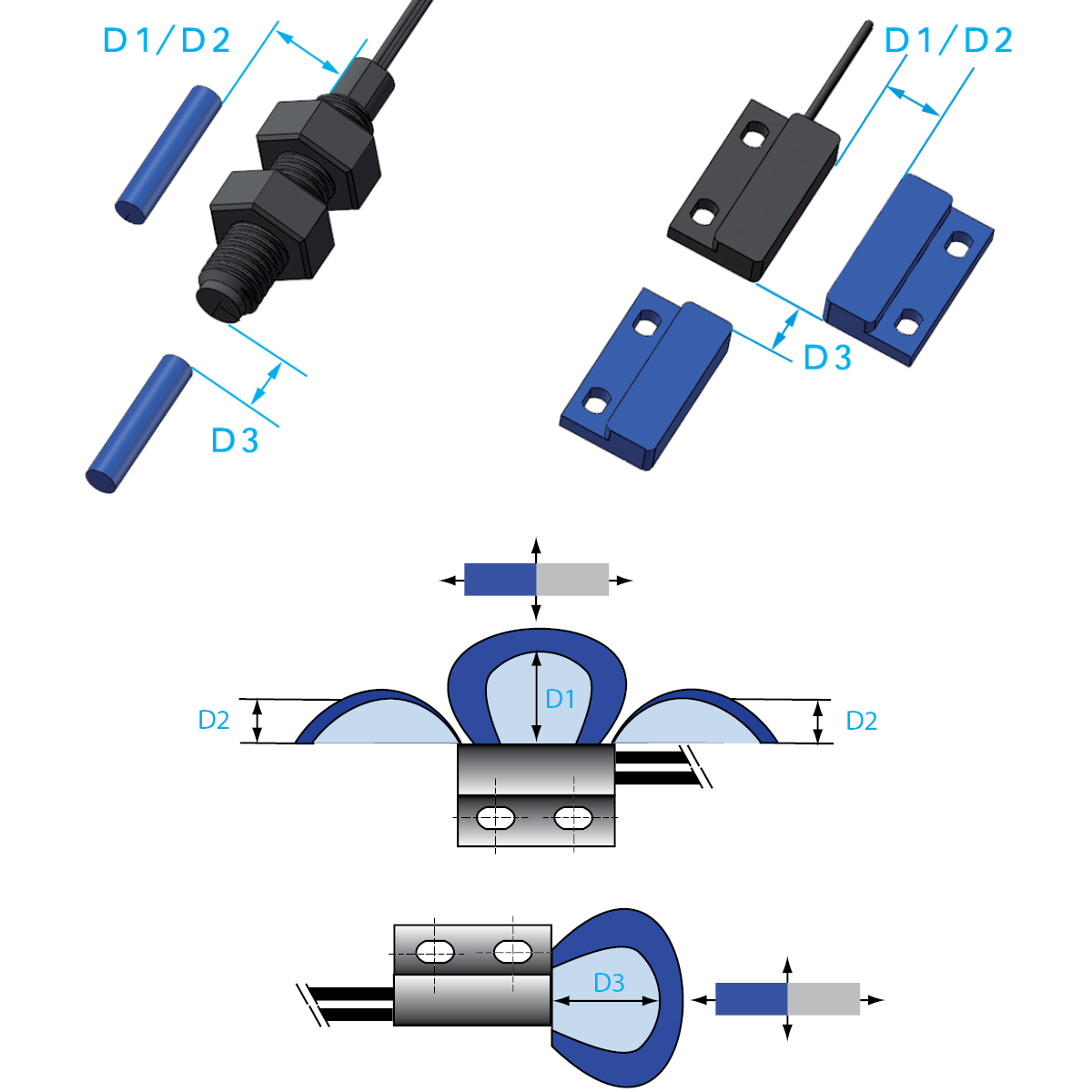
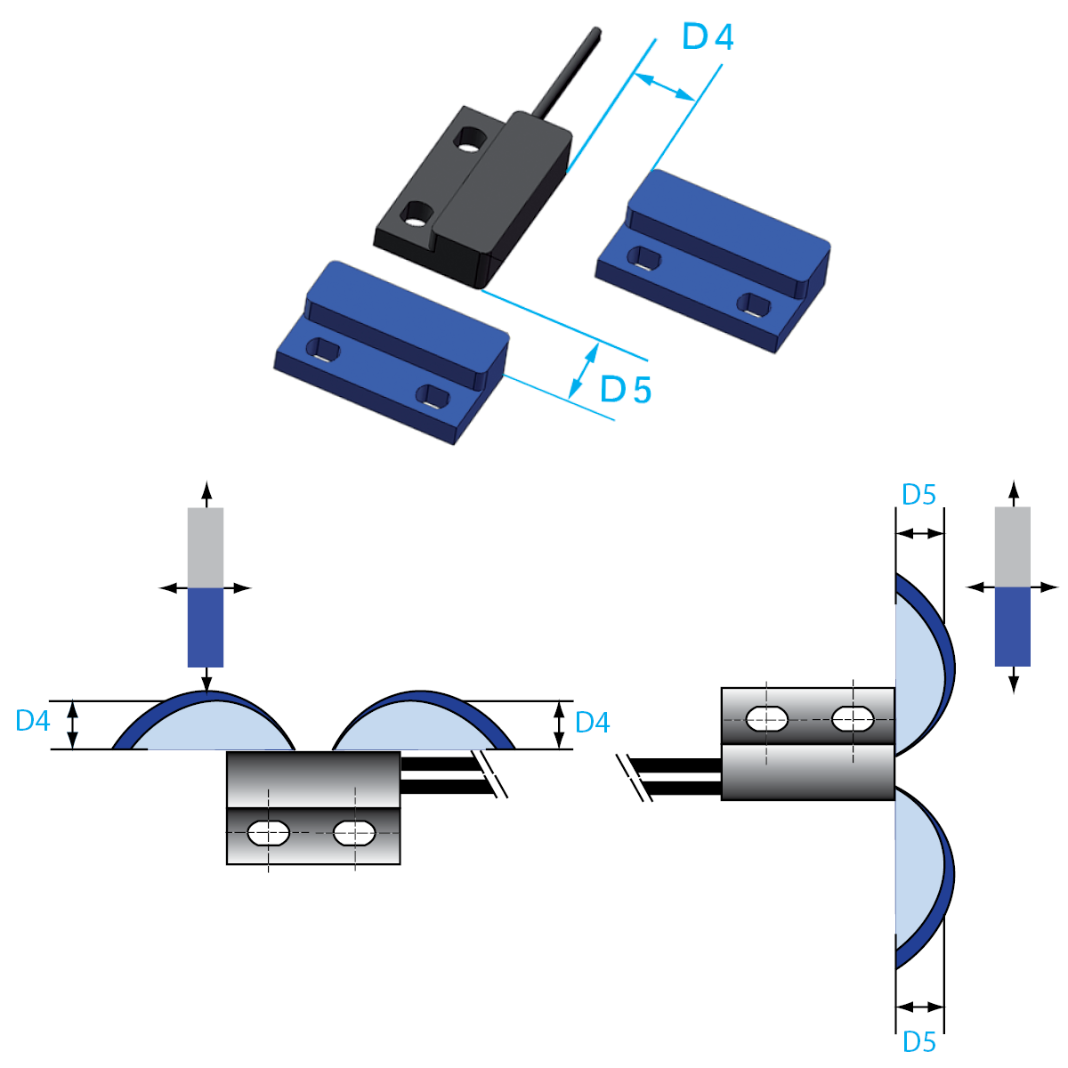
Activation Distance Tables and Diagrams
Explore detailed tables showing typical activation distances for different sensor series and magnet orientations. For quick reference, diagrams illustrate positions D1–D5 representing different orientations and movements of the actuator magnet relative to the sensor.
Key Terms:
- Magnetic Sensitivity (mT): Indicates how responsive the sensor is to magnetic fields.
- Activation (Pull-in) Distance: The maximum distance at which the sensor will activate when the magnet approaches.
- Deactivation (Drop-out) Distance: The minimum distance at which the sensor will deactivate as the magnet moves away.
- Reference Magnets: Specifications are valid for standard magnets such as M02, M04, M05, M13, and M21/P1 and M21P/2 screw magnets, and cylindrical magnets (ø 4×19 mm).
Key Notes:
- Distances are typical values and may vary depending on application conditions.
- The tables include part numbers, sensor types, and corresponding activation/deactivation distances for quick reference.
Activation Distance Table: Magnet Parallel to the Reed Sensor
Select a Reed Sensor Series below to view the corresponding activation and deactivation distances with the magnet positioned parallel (D1-D3 position variation) to the Reed Sensor.
Magnet Parallel
MK03 Series Reed Sensor
| Part-No. | Magnetic Sensitivity (mT) | Pull-in Drop-out Max. D1 | Pull-in Drop-out Max. D2 | Pull-in Drop-out Max. D3 |
| MK03-1A66B-500W | > 1.70 mT | 15.0 mm 17.5 mm | 6.5 mm 8.0 mm | 9.3 mm 11.4 mm |
| MK03-1A66C-500W | > 2.30 mT | 13.0 mm 16.5 mm | 4.4 mm 6.5 mm | 7.4 mm 9.9 mm |
| MK03-1A66D-500W | > 2.70 mT | 11.0 mm 14.5 mm | 4.0 mm 5.5 mm | 5.7 mm 8.5 mm |
| MK03-1A66E-500W | > 3.10 mT | 10.0 mm 13.5 mm | 3.5 mm 5.0 mm | 4.5 mm 8.0 mm |
The table on this page contains only part of the Standex Detect sensor product range. Switching distances for other series, switch types, special sensors and with other magnets can be obtained upon request.
Magnet Parallel
MK04 Series Reed Sensor
| Part-No. | Magnetic Sensitivity (mT) | Pull-in Drop-out Max. D1 | Pull-in Drop-out Max. D2 | Pull-in Drop-out Max. D3 |
| MK04-1A66B-500W | > 1.70 mT | 15.0 mm 17.5 mm | 6.5 mm 8.0 mm | 9.3 mm 11.4 mm |
| MK04-1A66C-500W | > 2.30 mT | 13.0 mm 16.5 mm | 4.4 mm 6.5 mm | 7.4 mm 9.9 mm |
| MK04-1A66D-500W | > 2.70 mT | 11.0 mm 14.5 mm | 4.0 mm 5.5 mm | 5.7 mm 8.5 mm |
| MK04-1A66E-500W | > 3.10 mT | 10.0 mm 13.5 mm | 3.5 mm 5.0 mm | 4.5 mm 8.0 mm |
The table on this page contains only part of the Standex Detect sensor product range. Switching distances for other series, switch types, special sensors and with other magnets can be obtained upon request.
Magnet Parallel
MK05 Series Reed Sensor
| Part-No. | Magnetic Sensitivity (mT) | Pull-in Drop-out Max. D1 | Pull-in Drop-out Max. D2 | Pull-in Drop-out Max. D3 |
| MK05-1A66B-500W | > 1.70 mT | 15.0 mm 17.5 mm | 6.5 mm 8.0 mm | 9.3 mm 11.4 mm |
| MK05-1A66C-500W | > 2.30 mT | 13.0 mm 16.5 mm | 4.4 mm 6.5 mm | 7.4 mm 9.9 mm |
| MK05-1A66D-500W | > 2.70 mT | 11.0 mm 14.5 mm | 4.0 mm 5.5 mm | 5.7 mm 8.5 mm |
| MK05-1A66E-500W | > 3.10 mT | 10.0 mm 13.5 mm | 3.5 mm 5.0 mm | 4.5 mm 8.0 mm |
The table on this page contains only part of the Standex Detect sensor product range. Switching distances for other series, switch types, special sensors and with other magnets can be obtained upon request.
Magnet Parallel
MK06 Series Reed Switch
| Part-No. | Magnetic Sensitivity (mT) | Pull-in Drop-out Max. D1 | Pull-in Drop-out Max. D2 | Pull-in Drop-out Max. D3 |
| MK06-4-A | > 1.70 mT | 18.0 mm 19.5 mm | 8.5 mm 9.5 mm | 15.0 mm 16.0 mm |
| MK06-4-B | > 1.70 mT | 16.0 mm 17.0 mm | 7.5 mm 8.0 mm | 12.5 mm 13.5 mm |
| MK06-4-C | > 2.30 mT | 14.0 mm 16.0 mm | 7.0 mm 7.5 mm | 10.5 mm 13.0 mm |
| MK06-4-D | > 2.70 mT | 13.0 mm 15.0 mm | 6.5 mm 7.0 mm | 10.0 mm 11.5 mm |
| MK06-4-E | > 3.10 mT | 12.0 mm 13.0 mm | 5.5 mm 6.0 mm | 8.5 mm 9.5 mm |
The table on this page contains only part of the Standex Detect sensor product range. Switching distances for other series, switch types, special sensors and with other magnets can be obtained upon request.
Magnet Parallel
MK11 Series Reed Sensor
| Part-No. | Magnetic Sensitivity (mT) | Pull-in Drop-out Max. D1 | Pull-in Drop-out Max. D2 | Pull-in Drop-out Max. D3 |
| MK11/M8-1A66B-500W | > 1.70 mT | 15.0 mm 17.5 mm | 6.5 mm 8.0 mm | 9.3 mm 11.4 mm |
| MK11/M8-1A66C-500W | > 2.30 mT | 13.0 mm 16.5 mm | 4.4 mm 6.5 mm | 7.4 mm 9.9 mm |
| MK11/M8-1A66D-500W | > 2.70 mT | 11.0 mm 14.5 mm | 4.0 mm 5.5 mm | 5.7 mm 8.5 mm |
| MK11/M8-1A66E-500W | > 3.10 mT | 10.0 mm 13.5 mm | 3.5 mm 5.0 mm | 4.5 mm 8.0 mm |
The table on this page contains only part of the Standex Detect sensor product range. Switching distances for other series, switch types, special sensors and with other magnets can be obtained upon request.
Magnet Parallel
MK13 Series Reed Sensor
| Part-No. | Magnetic Sensitivity (mT) | Pull-in Drop-out Max. D1 | Pull-in Drop-out Max. D2 | Pull-in Drop-out Max. D3 |
| MK13-1A66B-500W | > 1.70 mT | 15.0 mm 17.5 mm | 6.5 mm 8.0 mm | 9.3 mm 11.4 mm |
| MK13-1A66C-500W | > 2.30 mT | 13.0 mm 16.5 mm | 4.4 mm 6.5 mm | 7.4 mm 9.9 mm |
| MK13-1A66D-500W | > 2.70 mT | 11.0 mm 14.5 mm | 4.0 mm 5.5 mm | 5.7 mm 8.5 mm |
| MK13-1A66E-500W | > 3.10 mT | 10.0 mm 13.5 mm | 3.5 mm 5.0 mm | 4.5 mm 8.0 mm |
The table on this page contains only part of the Standex Detect sensor product range. Switching distances for other series, switch types, special sensors and with other magnets can be obtained upon request.
Magnet Parallel
MK14 Series Reed Sensor
| Part-No. | Magnetic Sensitivity (mT) | Pull-in Drop-out Max. D1 | Pull-in Drop-out Max. D2 | Pull-in Drop-out Max. D3 |
| MK14-1A66B-100W | > 1.70 mT | 15.0 mm 16.0 mm | 7.0 mm 8.0 mm | 11.0 mm 12.0 mm |
| MK14-1A66C-100W | > 2.30 mT | 11.0 mm 13.0 mm | 5.0 mm 6.5 mm | 8.0 mm 10.0 mm |
| MK14-1A66D-100W | > 2.70 mT | 10.0 mm 12.0 mm | 4.0 mm 5.0 mm | 6.0 mm 8.0 mm |
| MK14-1A66E-100W | > 3.10 mT | 9.0 mm 11.0 mm | 3.0 mm 4.5 mm | 4.0 mm 7.0 mm |
The table on this page contains only part of the Standex Detect sensor product range. Switching distances for other series, switch types, special sensors and with other magnets can be obtained upon request.
Magnet Parallel
MK15 Series Surface Mount Reed Switch
| Part-No. | Magnetic Sensitivity (mT) | Pull-in Drop-out Max. D1 | Pull-in Drop-out Max. D2 | Pull-in Drop-out Max. D3 |
| MK15-B-2 | > 1.70 mT | 14.0 mm 16.0 mm | 6.5 mm 8.0 mm | 7.0 mm 9.0 mm |
| MK15-C-2 | > 2.30 mT | 13.0 mm 15.0 mm | 6.0 mm 7.5 mm | 6.5 mm 8.5 mm |
| MK15-D-3 | > 2.70 mT | 12.0 mm 14.0 mm | 5.5 mm 7.0 mm | 6.0 mm 8.0 mm |
| MK15-E-3 | > 3.10 mT | 11.0 mm 13.0 mm | 5.0 mm 6.0 mm | 4.5 mm 7.0 mm |
The table on this page contains only part of the Standex Detect sensor product range. Switching distances for other series, switch types, special sensors and with other magnets can be obtained upon request.
Magnet Parallel
MK16 Series Surface Mount Reed Switch
| Part-No. | Magnetic Sensitivity (mT) | Pull-in Drop-out Max. D1 | Pull-in Drop-out Max. D2 | Pull-in Drop-out Max. D3 |
| MK16-B-2 | > 1.70 mT | 15.0 mm 16.0 mm | 7.0 mm 8.0 mm | 11.0 mm 12.0 mm |
| MK16-C-2 | > 2.30 mT | 13.0 mm 14.5 mm | 6.0 mm 7.0 mm | 8.0 mm 10.0 mm |
| MK16-D-2 | > 2.70 mT | 12.0 mm 14.0 mm | 5.5 mm 6.5 mm | 7.0 mm 9.0 mm |
| MK16-E-2 | > 3.10 mT | 11.0 mm 13.5 mm | 5.0 mm 6.0 mm | 6.0 mm 9.5 mm |
The table on this page contains only part of the Standex Detect sensor product range. Switching distances for other series, switch types, special sensors and with other magnets can be obtained upon request.
Magnet Parallel
MK17 Series Surface Mount Reed Switch
| Part-No. | Magnetic Sensitivity (mT) | Pull-in Drop-out Max. D1 | Pull-in Drop-out Max. D2 | Pull-in Drop-out Max. D3 |
| MK17-B-2 | > 1.70 mT | 15.0 mm 16.0 mm | 7.5 mm 8.0 mm | 12.5 mm 13.5 mm |
| MK17-C-2 | > 2.30 mT | 14.5 mm 15.5 mm | 7.0 mm 7.5 mm | 10.0 mm 11.5 mm |
| MK17-D-2 | > 2.70 mT | 12.5 mm 14.0 mm | 6.0 mm 7.0 mm | 9.5 mm 11.0 mm |
| MK17-E-2 | > 3.10 mT | 12.0 mm 13.5 mm | 5.5 mm 6.5 mm | 8.5 mm 10.5 mm |
The table on this page contains only part of the Standex Detect sensor product range. Switching distances for other series, switch types, special sensors and with other magnets can be obtained upon request.
Magnet Parallel
MK18 Series Reed Sensor
| Part-No. | Magnetic Sensitivity (mT) | Pull-in Drop-out Max. D1 | Pull-in Drop-out Max. D2 | Pull-in Drop-out Max. D3 |
| MK18-B-300W | > 1.70 mT | 16.5 mm 17.5 mm | 8.0 mm 9.5 mm | 14.5 mm 16.5 mm |
| MK18-C-300W | > 2.30 mT | 14.0 mm 15.5 mm | 7.0 mm 8.0 mm | 11.0 mm 12.5 mm |
| MK18-D-300W | > 2.70 mT | 12.0 mm 14.0 mm | 5.5 mm 7.5 mm | 9.0 mm 11.0 mm |
| MK18-E-300W | > 3.10 mT | 11.0 mm 13.5 mm | 5.0 mm 7.0 mm | 7.0 mm 10.5 mm |
The table on this page contains only part of the Standex Detect sensor product range. Switching distances for other series, switch types, special sensors and with other magnets can be obtained upon request.
Magnet Parallel
MK20/1 Series Reed Sensor
| Part-No. | Magnetic Sensitivity (mT) | Pull-in Drop-out Max. D1 | Pull-in Drop-out Max. D2 | Pull-in Drop-out Max. D3 |
| MK20/1-B-100W | > 1.70 mT | 11.0 mm 11.5 mm | 5.5 mm 6.0 mm | 9.0 mm 10.0 mm |
| MK20/1-C-100W | > 2.30 mT | 10.5 mm 11.0 mm | 5.0 mm 5.5 mm | 8.0 mm 9.0 mm |
| MK20/1-D-100W | > 2.70 mT | 10.0 mm 10.5 mm | 4.5 mm 5.0 mm | 7.0 mm 8.0 mm |
| MK20/1-E-100W | > 3.10 mT | 9.5 mm 10.0 mm | 4.0 mm 4.5 mm | 6.0 mm 7.0 mm |
The table on this page contains only part of the Standex Detect sensor product range. Switching distances for other series, switch types, special sensors and with other magnets can be obtained upon request.
Magnet Parallel
MK21 Series Reed Sensor
| Part-No. | Magnetic Sensitivity (mT) | Pull-in Drop-out Max. D1 | Pull-in Drop-out Max. D2 | Pull-in Drop-out Max. D3 |
| MK21M/1A66B-500W | > 1.70 mT | 13.0 mm 14.0 mm | 5.5 mm 6.5 mm | 4.5 mm 5.5 mm |
| MK21M/1A66C-500W | > 2.30 mT | 11.0 mm 13.0 mm | 4.0 mm 6.0 mm | 2.5 mm 4.5 mm |
| MK21M/1A66D-500W | > 2.70 mT | 9.5 mm 11.5 mm | 3.5 mm 5.0 mm | 1.0 mm 2.5 mm |
| MK21M/1A66E-500W | > 3.10 mT | 8.0 mm 10.0 mm | 2.5 mm 3.5 mm |
The table on this page contains only part of the Standex Detect sensor product range. Switching distances for other series, switch types, special sensors and with other magnets can be obtained upon request.
Activation Table: Magnet Perpendicular to the Reed Sensor
Select a Reed Sensor Series below to view the corresponding activation and deactivation distances with the magnet positioned perpendicular (D4-D5 position variation) to the Reed Sensor.
Magnet Perpendicular
MK03 Series Reed Sensor
| Part-No. | Magnetic Sensitivity (mT) | Pull-in Drop-out Max. D4 | Pull-in Drop-out Max. D5 |
| MK03-1A66B-500W | > 1.70 mT | 8.5 mm 10.1 mm | 8.5 mm 10.1 mm |
| MK03-1A66C-500W | > 2.30 mT | 7.2 mm 9.5 mm | 7.2 mm 9.5 mm |
| MK03-1A66D-500W | > 2.70 mT | 6.5 mm 9.0 mm | 6.5 mm 9.0 mm |
| MK03-1A66E-500W | > 3.10 mT | 5.7 mm 8.5 mm | 5.7 mm 8.5 mm |
The table on this page contains only part of the Standex Detect sensor product range. Switching distances for other series, switch types, special sensors and with other magnets can be obtained upon request.
Magnet Perpendicular
MK04 Series Reed Sensor
| Part-No. | Magnetic Sensitivity (mT) | Pull-in Drop-out Max. D4 | Pull-in Drop-out Max. D5 |
| MK04-1A66B-500W | > 1.70 mT | 8.5 mm 10.1 mm | 8.5 mm 10.1 mm |
| MK04-1A66C-500W | > 2.30 mT | 7.2 mm 9.5 mm | 7.2 mm 9.5 mm |
| MK04-1A66D-500W | > 2.70 mT | 6.5 mm 9.0 mm | 6.5 mm 9.0 mm |
| MK04-1A66E-500W | > 3.10 mT | 5.7 mm 8.5 mm | 5.7 mm 8.5 mm |
The table on this page contains only part of the Standex Detect sensor product range. Switching distances for other series, switch types, special sensors and with other magnets can be obtained upon request.
Magnet Perpendicular
MK05 Series Reed Sensor
| Part-No. | Magnetic Sensitivity (mT) | Pull-in Drop-out Max. D4 | Pull-in Drop-out Max. D5 |
| MK05-1A66B-500W | > 1.70 mT | 8.5 mm 10.1 mm | 8.5 mm 10.1 mm |
| MK05-1A66C-500W | > 2.30 mT | 7.2 mm 9.5 mm | 7.2 mm 9.5 mm |
| MK05-1A66D-500W | > 2.70 mT | 6.5 mm 9.0 mm | 6.5 mm 9.0 mm |
| MK05-1A66E-500W | > 3.10 mT | 5.7 mm 8.5 mm | 5.7 mm 8.5 mm |
The table on this page contains only part of the Standex Detect sensor product range. Switching distances for other series, switch types, special sensors and with other magnets can be obtained upon request.
Magnet Perpendicular

MK06 Series Reed Switch
| Part-No. | Magnetic Sensitivity (mT) | Pull-in Drop-out Max. D4 | Pull-in Drop-out Max. D5 |
| MK06-4-A | > 1.70 mT | 12.0 mm 13.5 mm | 13.5 mm 15.0 mm |
| MK06-4-B | > 1.70 mT | 10.5 mm 11.5 mm | 11.0 mm 12.0 mm |
| MK06-4-C | > 2.30 mT | 9.5 mm 11.0 mm | 9.5 mm 12.0 mm |
| MK06-4-D | > 2.70 mT | 9.0 mm 10.0 mm | 9.0 mm 10.5 mm |
| MK06-4-E | > 3.10 mT | 8.0 mm 9.0 mm | 8.0 mm 9.0 mm |
The table on this page contains only part of the Standex Detect sensor product range. Switching distances for other series, switch types, special sensors and with other magnets can be obtained upon request.
Magnet Perpendicular
MK11 Series Reed Sensor
| Part-No. | Magnetic Sensitivity (mT) | Pull-in Drop-out Max. D4 | Pull-in Drop-out Max. D5 |
| MK11/M8-1A66B-500W | > 1.70 mT | 8.5 mm 10.1 mm | 8.5 mm 10.1 mm |
| MK11/M8-1A66C-500W | > 2.30 mT | 7.2 mm 9.5 mm | 7.2 mm 9.5 mm |
| MK11/M8-1A66D-500W | > 2.70 mT | 6.5 mm 9.0 mm | 6.5 mm 9.0 mm |
| MK11/M8-1A66E-500W | > 3.10 mT | 5.7 mm 8.5 mm | 5.7 mm 8.5 mm |
The table on this page contains only part of the Standex Detect sensor product range. Switching distances for other series, switch types, special sensors and with other magnets can be obtained upon request.
Magnet Perpendicular
MK13 Series Reed Sensor
| Part-No. | Magnetic Sensitivity (mT) | Pull-in Drop-out Max. D4 | Pull-in Drop-out Max. D5 |
| MK13-1A66B-500W | > 1.70 mT | 8.5 mm 10.1 mm | 8.5 mm 10.1 mm |
| MK13-1A66C-500W | > 2.30 mT | 7.2 mm 9.5 mm | 7.2 mm 9.5 mm |
| MK13-1A66D-500W | > 2.70 mT | 6.5 mm 9.0 mm | 6.5 mm 9.0 mm |
| MK13-1A66E-500W | > 3.10 mT | 5.7 mm 8.5 mm | 5.7 mm 8.5 mm |
The table on this page contains only part of the Standex Detect sensor product range. Switching distances for other series, switch types, special sensors and with other magnets can be obtained upon request.
Magnet Perpendicular
MK14 Series Reed Sensor
| Part-No. | Magnetic Sensitivity (mT) | Pull-in Drop-out Max. D4 | Pull-in Drop-out Max. D5 |
| MK14-1A66B-100W | > 1.70 mT | 10 mm 12.0 mm | 8.0 mm 9.0 mm |
| MK14-1A66C-100W | > 2.30 mT | 9.0 mm 11.0 mm | 6.0 mm 7.5 mm |
| MK14-1A66D-100W | > 2.70 mT | 6.0 mm 8.0 mm | 4.5 mm 6.5 mm |
| MK14-1A66E-100W | > 3.10 mT | 4.0 mm 6.0 mm | 2.5 mm 5.0 mm |
The table on this page contains only part of the Standex Detect sensor product range. Switching distances for other series, switch types, special sensors and with other magnets can be obtained upon request.
Magnet Perpendicular
MK15 Series Surface Mount Reed Switch
| Part-No. | Magnetic Sensitivity (mT) | Pull-in Drop-out Max. D4 | Pull-in Drop-out Max. D5 |
| MK15-B-2 | > 1.70 mT | 9.0 mm 9.5 mm | 7.0 mm 8.0 mm |
| MK15-C-2 | > 2.30 mT | 8.5 mm 9.0 mm | 6.5 mm 7.5 mm |
| MK15-D-3 | > 2.70 mT | 7.5 mm 8.5 mm | 5.5 mm 7.0 mm |
| MK15-E-3 | > 3.10 mT | 7.0 mm 8.0 mm | 3.5 mm 6.0 mm |
The table on this page contains only part of the Standex Detect sensor product range. Switching distances for other series, switch types, special sensors and with other magnets can be obtained upon request.
Magnet Perpendicular
MK16 Series Surface Mount Reed Switch
| Part-No. | Magnetic Sensitivity (mT) | Pull-in Drop-out Max. D4 | Pull-in Drop-out Max. D5 |
| MK16-B-2 | > 1.70 mT | 10.0 mm 11.0 mm | 9.5 mm 11.0 mm |
| MK16-C-2 | > 2.30 mT | 8.0 mm 10.0 mm | 8.0 mm 9.5 mm |
| MK16-D-2 | > 2.70 mT | 7.5 mm 9.5 mm | 7.0 mm 9.0 mm |
| MK16-E-2 | > 3.10 mT | 7.0 mm 9.0 mm | 7.0 mm 8.5 mm |
The table on this page contains only part of the Standex Detect sensor product range. Switching distances for other series, switch types, special sensors and with other magnets can be obtained upon request.
Magnet Perpendicular
MK17 Series Reed Switch
| Part-No. | Magnetic Sensitivity (mT) | Pull-in Drop-out Max. D4 | Pull-in Drop-out Max. D5 |
| MK17-B-2 | > 1.70 mT | 10.0 mm 11.0 mm | 11.0 mm 12.0 mm |
| MK17-C-2 | > 2.30 mT | 9.0 mm 10.0 mm | 9.5 mm 10.5 mm |
| MK17-D-2 | > 2.70 mT | 8.0 mm 9.5 mm | 8.0 mm 9.5 mm |
| MK17-E-2 | > 3.10 mT | 7.5 mm 8.5 mm | 7.5 mm 9.0 mm |
The table on this page contains only part of the Standex Detect sensor product range. Switching distances for other series, switch types, special sensors and with other magnets can be obtained upon request.
Magnet Perpendicular
MK18 Series Reed Sensor
| Part-No. | Magnetic Sensitivity (mT) | Pull-in Drop-out Max. D2 | Pull-in Drop-out Max. D3 |
| MK18-B-300W | > 1.70 mT | 10.0 mm 10.5 mm | 12.0 mm 14.0 mm |
| MK18-C-300W | > 2.30 mT | 9.0 mm 10.0 mm | 9.5 mm 11.0 mm |
| MK18-D-300W | > 2.70 mT | 8.0 mm 9.5 mm | 8.0 mm 10.0 mm |
| MK18-E-300W | > 3.10 mT | 7.0 mm 9.0 mm | 7.0 mm 9.5 mm |
The table on this page contains only part of the Standex Detect sensor product range. Switching distances for other series, switch types, special sensors and with other magnets can be obtained upon request.
Magnet Perpendicular
MK20/1 Series Reed Sensor
| Part-No. | Magnetic Sensitivity (mT) | Pull-in Drop-out Max. D4 | Pull-in Drop-out Max. D5 |
| MK20/1-B-100W | > 1.70 mT | 6.5 mm 7.0 mm | 7.5 mm 8.0 mm |
| MK20/1-C-100W | > 2.30 mT | 6.0 mm 6.5 mm | 7.0 mm 7.5 mm |
| MK20/1-D-100W | > 2.70 mT | 5.5 mm 6.0 mm | 6.5 mm 7.0 mm |
| MK20/1-E-100W | > 3.10 mT | 5.0 mm 5.5 mm | 6.0 mm 6.5 mm |
The table on this page contains only part of the Standex Detect sensor product range. Switching distances for other series, switch types, special sensors and with other magnets can be obtained upon request.
Magnet Perpendicular
MK21 Series Reed Sensor
| Part-No. | Magnetic Sensitivity (mT) | Pull-in Drop-out Max. D4 | Pull-in Drop-out Max. D5 |
| MK21M/1A66B-500W | > 1.70 mT | 8.0 mm 9.0 mm | 3.0 mm 4.0mm |
| MK21M/1A66C-500W | > 2.30 mT | 6.5 mm 8.5 mm | 1.5 mm 3.5 mm |
| MK21M/1A66D-500W | > 2.70 mT | 5.0 mm 7.0 mm | 1.0 mm 2.0 mm |
| MK21M/1A66E-500W | > 3.10 mT | 4.0 mm 6.0 mm |
The table on this page contains only part of the Standex Detect sensor product range. Switching distances for other series, switch types, special sensors and with other magnets can be obtained upon request.
Actuator Magnets
All activation distance data above are valid for the actuator magnets listed below:
Summary: Best Practices for Reliable Reed Sensor Design
To ensure accurate activation, keep magnet orientation consistent, use recommended magnet sizes, and validate distances under real-world conditions. Avoid common pitfalls such as using magnets that are too weak or placing sensors in areas with high magnetic interference. Following these guidelines helps achieve dependable performance and long-term reliability in your applications.
Additional Resources
For more information on magnetic interaction, check out the Reed Technology Academy. Designed for engineers, this resource delivers practical insights to help you optimize performance, improve reliability, and make smarter design decisions using Reed Technology.
The Magnet Interaction page is where you can see up to 14 sensing animations, showing various magnet position and movement applications like the example here.